Very Small Package (VSP) Handling and Teach Considerations
Summary
Checklist for successfully teaching and handling VSP Devices.
Details
Note that the BPM Microsystems specification sheet lists the SOT23 at 2.95 mm by 1.63 mm as the smallest device supported. Devices smaller than this will not be
supported,
or will require special setup techniques.
The following should be performed in this order to ensure success.
- Use the Correct Nozzle Tip.
Use the smallest nozzle (part number: CPICNOZXG) and remove the O-Ring. - Check the Nozzle Tip for BurrsInspect the nozzle tip under a microscope looking for machining burrs, or anything that would prevent the device from sealing completely on the nozzle tip. If metal burrs are found, use a procedure called lapping to remove them. Google 'lapping', or try these two links to get the idea:
- How to Lap a Heatsink Guide,
- Hone Lapping 101).
The purpose is to ensure that the nozzle tip surface is perfectly parallel to the Cyberoptic camera.
- How to Lap a Heatsink Guide,
- Check the Z Bellows.
The spring action of the Z bellows should be stiff. If the spring action is soft or loose, replace the Z bellows (part number: CPICROD01) - Check the Nozzle Run-Out.
Make sure that the nozzle run-out is 2 mils or less. Get the nozzle run-out as close to 0 as possible. The higher the run-out, the more teaching and handling problems there will be. Note: the run-out will be listed in the BPWin output window or can be found in the data log file at c:\bp\datalog\blackbox.html. - Check the Camera to Nozzle Coplanarity Alignment.
The alignment can get knocked out of tolerance during shipping. This should be checked regardless. Nozzle run-out will be critical at this point. Try to get the nozzle in the middle of the camera field. This will minimize side-to-side variations after coplanarity alignment.
This is a link to a step-by-step procedure document: Camera to Nozzle Coplanar Alignment (link opens a new tab/window)
The Camera Coplanarity alignment cannot be stressed enough! It must be done, and it must be done correctly! - Check the Camera-to-Nozzle Offset.This is only applicable on the 4000 SeriesAutohandler. Incorrect values are amplified during VSP teaches.
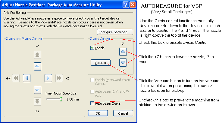
- Use the AutoMeasure Function.
Run AutoMeasure to get a good Alignment Offset. The Alignment Offset may vary from machine to machine due to factors such as Z bellows spring compression, etc.
This Alignment Offset is a good starting point. Tweaking may and probably will be necessary during a job. If the Alignment Offset is a value close to zero, or even a negative number, then the Z bellows is worn and must be replaced. (part number: CPICROD01) - Use the ManualZ AxisControl when teaching.This technique can also be used for AutoMeasure. In the Teach window, check the Z axisControl box to enable the manual Z control function. Drive the Z axis down while watching the nozzle tip to help set the Z height. For 3000 Series Autohandlers, this technique will achieve a much more accurate X and Y axis alignment than the laser pointer will allow.

- Check the Package Dimensions.Let AutoMeasure determine the length and width. These will be good startingpoints,but may need to be adjusted during a job session.Set the Pick-Up Offset value at about 15 mils. (mispicksmay require changing the value to 20 mils.)Set the Placement Offset value at about -10 to -15. (misplacements would indicate that devices are dropping from too high a location,soreduce the value.)Set the Tolerance value at 5%. Lower values will increase alignment failures. Higher values may pass bent pins.
- Adjust Puff-Off
Puff-off is critical. A smaller inner diameter nozzle will require a higher puff-off pressure to accomplish the same results. Too much puff-off could flip the device in the socket or even blow the device out of the socket. Too low a puff-off pressure will allow the device to "stick" to the nozzle, resulting in an accidental misplacement. It is misplacements like this that result in bent leads. A Puff-off change as little as 1 PSI can have a dramatic effect. Tip: Place the device on a white piece of paper on a tray platform or shuttle to simulate a socket teach. You will be able to see the device and nozzle clearly and can visually judge the results of puff-off settings.
Common error messages and issues that can be encountered during teach:
Message: Failed to learn device location.
Go to C:\BP\Data Log and open the BlackBox.html file. Scroll to the end of the file and find the error message. You can also search for the error message in the log file by using CTRL+F and typing the detail you would like to search. Typically the measurement will be out of tolerance of the length or width. The actual measured length or width will be displayed. Enter the measured value into the package teach window and try the teach again. In the log file, look for Cyber Status codes before the error. A Cyber Status code of 1 signifies a good measurement. Any code other than 1 is a problem code. Please refer to this pdf file for a list of the Cyberoptic codes: 
Contact BPM Microsystems Technical Support for further explanation of your specific code if further details or assistance is needed.
Message: The Angle Limit was reached before a minimum width was detected, or the device slipped on the nozzle.
Check for Vacuum System Problems. Weak vacuum at the nozzle can allow the device to slip on the nozzle. Reference the following documents for low vacuum pressure issues:
3000 series: Vacuum pressure too low on 3000 Series APS
4000 series: Vacuum pressure too low on 4000 Series APS
Tape loader problems:
The TM50 can be used with either heat
of
pressure sealing. The TM300 can only be used with pressure sealing because the actuation of the heat sealer will cause the devices to jump out of the carrier tape. Use the slowest speed setting of 5 to minimize carrier tape jolting. We have also found that certain cover tapes can actually stick to the guide rods and cause devices to pop out of the carrier pockets. In some cases, it may be necessary to machine a cover plate out of ESD plexiglass to cover the tape loader track and open carrier tape to prevent placed devices from jumping out of the carrier tape pockets.
Related Articles
Device Package Parameters
Device Package Dimensions The CyberOptics laser alignment camera is the heart of the vision centering system and you will need to specify the dimensions of your device. A library of package types comes with the BPWin software. The settings for a ...Automated Package Measure Utility
Summary The purpose of this utility is to facilitate entering package dimensions that include: Thickness of the package. Narrowest length of the package. Longest length of the package. Alignment offset that will obtain the best measurements during a ...Nozzle Runout
This test should be used to ensure that the Pick-and-Place nozzle is installed properly and that the CyberOptics Laser Align Camera will accurately measure a device during placement. A large runout can cause the CyberOptics Laser Align Camera to ...BPM Automated Pick and Place Issues
Indicators Pick errors, place errors or vision centering problems occur frequently during a job session. Troubleshoot Ensure that the stations and the package are taught correctly. This is the cause of the majority of Pick-and-Place problems. Run ...Do you have any idea of the life cycle for a socket module?
If properly cared for the socket module base, the part that connects to the programmer, should last for 10's of thousands of cycles, regardless of the package. It is important the care is taken during installation and removal of the module from the ...