No communication with Cyberoptics system
Summary
Handler cannot initialize because of lost communication with Cyberoptics system
Details
Not to be confused with Cyber Status 5 (no communication between the SCM board and the Camera)Typical log file snippet:
2010-10-18 13:23:18 -0800 Cyber Optics camera: Hardware handshaking is disabled.
2010-10-18 13:23:18 -0800 Cyber Optics camera: Baud rate setting is 57600.
2010-10-18 13:23:19 -0800 Cyber Optics camera: Serial COM port COM2 opened successfully but Cyber Optics camera could not be detected.
2010-10-18 13:23:19 -0800 Vision centering subsystem failed.
2010-10-18 13:23:21 -0800 Initialization of the Pick-and-Place controller and its components failed because the system could not initialize the Cyber Optics alignment camera.
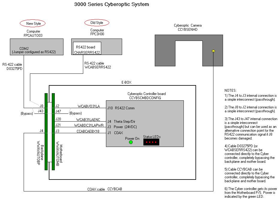
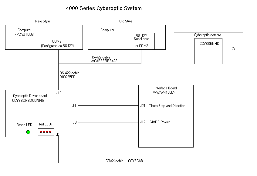
2010-10-18 13:23:21 -0800 The Pick-and-Place system did not initialize. The cause is a disconnect between the Handler computer's COM2 and the Cyber SCM board. Possible problems:
1) The RS 422 cable, D03275PD, is connected to COM1 not COM2. (Note: COM2 is jumper configured on the SBC, Single Board Computer, to RS422 serial protocol.)
2) The RS 422 cable, D03275PD, is defective.
3) For 3000 systems, the Blackplane top connector, J8, is defective. (Note: J8 is a passthrough to J2 on the Motherboard. If J8 connector is defective, move the D03275PD cable to J43 on the backplane, and also move the internal RS422 cable, WCABI/O31LA, to J47 on the motherboard.)
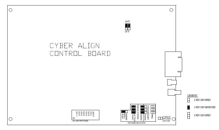
4) The SCM controller board, CCYBSCMBDCONFIG, is not configured correctly. Refer to chart for DIP switch and jumper settings.
5) The SCM controller board, CCYBSCMBDCONFIG, is defective.
6) The computer's COM2 port is defective.

Date Created
2014-12-04 15:55:07
2014-12-04 15:55:07
Date Updated
2014-12-04 15:55:07
2014-12-04 15:55:07
Related Articles
Cyber Status 5, Link Error
Summary Handler will not initialise. Log file shows Cyber Status 5, Link Error. Details Conditions: Handler will not initialise. There is no motion. Log file shows Cyber Status 5. The Cyberoptics error table states "Link Fail (Sensor Data Error)" A ...Why are devices being placed at an angle when using an Automated Programming System(APS)?
Summary Procedure to evaluate and troubleshoot why devices are placed at an angle. Details The angular placement can be any angle, 5 degree , 30 degree, 45 degree, 90 degree, etc. This angular placement can be seen in the sockets, tray, laser nozzles ...CyberOptics Image Quality Test
CyberOptics Camera Image Quality Test This test should be used to ensure that the CyberOptics Laser Align Camera is functioning properly and clear of debris. The test is automatically run at initialization and at the beginning of the job. Various ...BPM Automated Pick and Place Issues
Indicators Pick errors, place errors or vision centering problems occur frequently during a job session. Troubleshoot Ensure that the stations and the package are taught correctly. This is the cause of the majority of Pick-and-Place problems. Run ...TS1500 - USB Communication Problem
If you are experiencing issues with obtaining communication via USB to your TS1500 tray Stacker, then please read the following information. You need to ensure that the driver is correct and that you have only one instance of DUB-E100 listed in ...

